Between SIM-Cloud virtual routers behind NAT Traversal (VPNaaS-VPNaaS)
Description
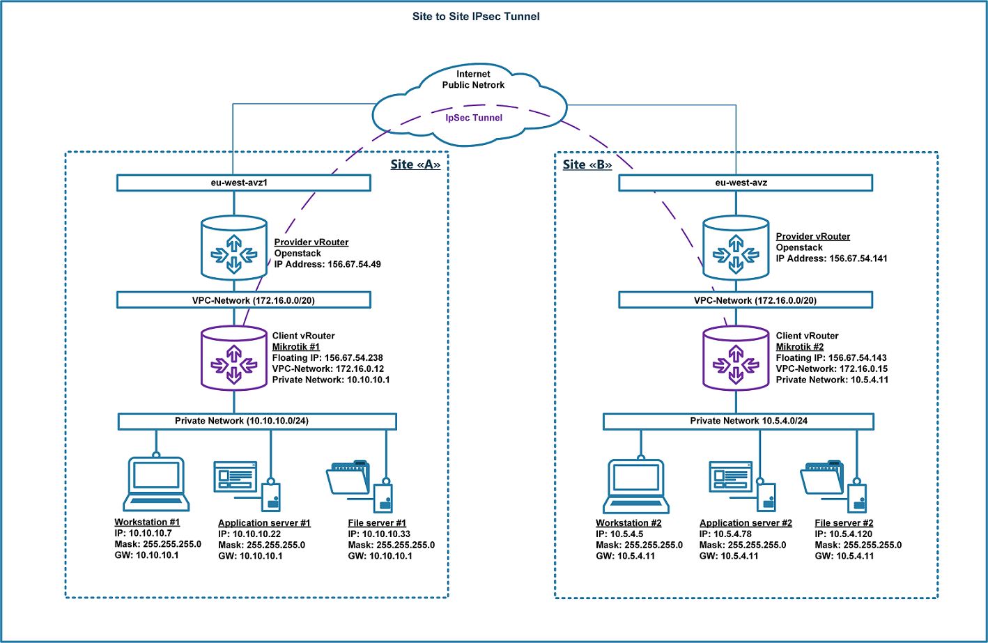
This example describes how to configure a site-to-site VPN connection, as shown below. Two remote virtual MikroTik routers connect to the public Internet through an intermediate network device—the provider’s router. Therefore, both MikroTik routers are behind NAT-T. This article provides examples of configuring the devices through both the command line and the graphical user interface (GUI) (WinBox).
Prerequisites
The workstations and the existing infrastructure are also behind NAT. Each site, Site “A” and Site “B”, has its own private subnet:
10.10.10.0/24 for Site “A”
10.5.4.0/24 for Site “B”
MikroTik router version: RouterOS 6.41.2 stable (CHR).
WinBox version: 3.18.
The connection and configuration steps may differ depending on the router OS and software versions.
Note
To establish a VPN connection, ensure that the following requirements are met:
Network connectivity between the routers:
Protocol: UDP, port 500 (for IKE, to manage encryption keys).
Protocol: UDP, port 4500 (for IPsec NAT-Traversal mode).
Protocol: ESP, value 50 (for IPsec).
Protocol: AH, value 51 (for IPsec).
Firewall rules must not block network traffic between the routers and private subnets.
The private subnets connected through IPsec must be different and must not overlap.
Client vRouter |
Floating IP |
VPC-Network IP |
Private Network IP |
Site “A” MikroTik #1 |
156.67.54.238/32 |
172.16.0.12/32 |
10.10.10.1/32 |
Site “B” MikroTik #2 |
156.67.54.143/32 |
172.16.0.15/32 |
10.5.4.11/32 |
This example performs the initial configuration of a secure site-to-site IPsec VPN connection between the private networks 10.10.10.0/24 and 10.5.4.0/24 behind the routers.
Site “A” configuration
1-A. Configure the IPsec peer. At this stage, configure the following parameters:
address (the address of the remote peer router),
auth-method (the authentication method),
secret (the pre-shared secret),
my-id (the local identifier).
Leave the other parameters at their default values. Configure these settings from the command line as follows:
/ip ipsec peer
add address=156.67.54.143/32 my-id=address:172.16.0.12 auth-method=pre-shared-key secret="123456"
Verify the changes:
[admin@Site "A"] > ip ipsec peer print
Flags: X - disabled, D - dynamic, R - responder
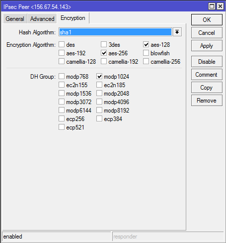
0      address=156.67.54.143/32 auth-method=pre-shared-key secret="123456" generate-policy=no policy-template-group=default exchange-mode=main
       send-initial-contact=yes nat-traversal=yes my-id=address:172.16.0.12 proposal-check=obey hash-algorithm=sha1
       enc-algorithm=aes-256,aes-128 dh-group=modp1024 lifetime=1d dpd-interval=2m dpd-maximum-failures=5
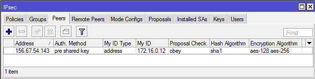
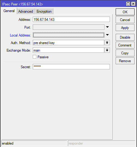
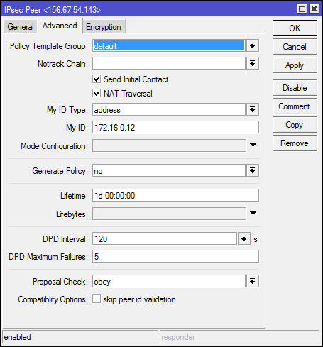
The output of the ip ipsec peer print command confirms that the parameters were
applied correctly. You can apply the same settings through the router’s graphical
user interface as follows:
2-A. For the following steps, the proposed authentication and encryption algorithms
must match on both routers. This example uses the default settings. To view and
verify the proposal settings, run ip ipsec proposal print:
[admin@Site "A"] > ip ipsec proposal print
Flags: X - disabled, * - default
 0  * name="default" auth-algorithms=sha1
      enc-algorithms=aes-256-cbc,aes-192-cbc,aes-128-cbc lifetime=30m
      pfs-group=modp1024
3-A. Define the IPsec policy:
/ip ipsec policy
add src-address=10.10.10.0/24 src-port=any dst-address=10.5.4.0/24 dst-port=any \
sa-src-address=172.16.0.12 sa-dst-address=156.67.54.143 \
tunnel=yes action=encrypt proposal=default
Verify the policy changes:
[admin@Site "A"] > ip ipsec policy print
Flags: T - template, X - disabled, D - dynamic, I - invalid, A - active, * - default
 0 T * group=default src-address=::/0 dst-address=::/0 protocol=all proposal=default template=yes
 1  A  src-address=10.10.10.0/24 src-port=any dst-address=10.5.4.0/24 dst-port=any protocol=all
       action=encrypt level=require ipsec-protocols=esp tunnel=yes sa-src-address=172.16.0.12
       sa-dst-address=156.67.54.143 proposal=default ph2-count=1
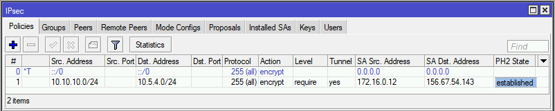
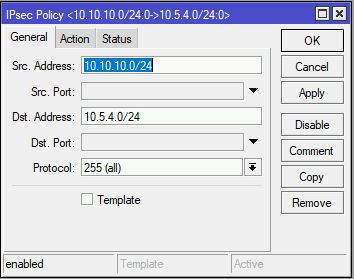
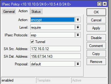
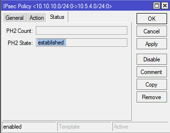
The output of the ip ipsec policy print command confirms that the parameters
were applied correctly. You can apply the same settings through the router’s
graphical user interface as follows:
After completing the previous three steps for the router at Site “A”, configure the router at Site “B”.
Site “B” configuration
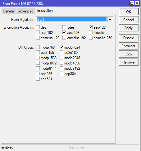
1-B. The IPsec peer configuration for Site “B” is almost identical to the Site “A”
configuration. Only two parameters differ: the remote peer IP address (address)
and the local identifier (my-id).
Configure these settings from the command line:
/ip ipsec peer
add address=156.67.54.238/32 my-id=address:172.16.0.15 auth-method=pre-shared-key secret="123456"
Verify the changes:
[admin@Site "B"] > ip ipsec peer print
Flags: X - disabled, D - dynamic, R - responder
 0     address=156.67.54.238/32 auth-method=pre-shared-key secret="123456" generate-policy=no
       policy-template-group=default exchange-mode=main send-initial-contact=yes nat-traversal=yes
       my-id=address:172.16.0.15 proposal-check=obey hash-algorithm=sha1 enc-algorithm=aes-256,aes-128
       dh-group=modp1024 lifetime=1d dpd-interval=2m dpd-maximum-failures=5
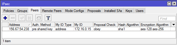
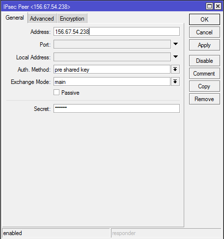
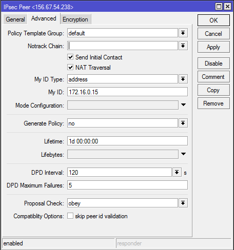
The output of the ip ipsec peer print command confirms that the parameters were
applied correctly. You can apply the same settings through the router’s graphical
user interface as follows:
2-B. Verify that the default proposal settings exist and match those on the Site “A” router:
[admin@Site "B"] > ip ipsec proposal print
Flags: X - disabled, * - default
 0  * name="default" auth-algorithms=sha1 enc-algorithms=aes-256-cbc,aes-192-cbc,aes-128-cbc lifetime=30m
      pfs-group=modp1024
The output of ip ipsec proposal print must match on both routers that form the
tunnel.
3-B. Create the IPsec policy at Site “B”:
/ip ipsec policy
add src-address=10.1.101.0/24 src-port=any dst-address=10.1.202.0/24 dst-port=any \
sa-src-address=192.168.80.1 sa-dst-address=192.168.90.1 \
tunnel=yes action=encrypt proposal=default
Verify the policy changes:
[admin@Site "B"] > ip ipsec policy print
Flags: T - template, X - disabled, D - dynamic, I - invalid, A - active, * - default
 0 T * group=default src-address=::/0 dst-address=::/0 protocol=all proposal=default template=yes
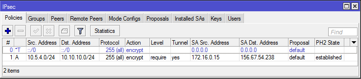
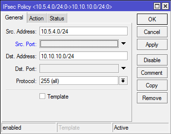
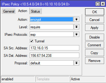
 1  A  src-address=10.5.4.0/24 src-port=any dst-address=10.10.10.0/24 dst-port=any protocol=all
       action=encrypt level=require ipsec-protocols=esp tunnel=yes sa-src-address=172.16.0.15
       sa-dst-address=156.67.54.238 proposal=default ph2-count=1
The output of the ip ipsec policy print command confirms that the parameters
were applied correctly. You can apply the same settings through the router’s
graphical user interface as follows:
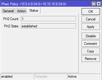
After steps 1-A through 3-A and 1-B through 3-B are completed correctly, the tunnel should be established and two security associations should be created on both routers.
To verify the VPN connection, run ip ipsec remote-peers print and
ip ipsec installed-sa print on both routers.
[admin@Site "A"] > ip ipsec remote-peers print
Flags: R - responder, N - natt-peer
 #    ID     STATE              REMOTE-ADDRESS   DYNAMIC-ADDRESS    UPTIME
 0 RN        established        156.67.54.143                       7h55m41s


[admin@Site "B"] > ip ipsec remote-peers print
Flags: R - responder, N - natt-peer
 #    ID     STATE              REMOTE-ADDRESS  DYNAMIC-ADDRESS    UPTIME
 0  N        established        156.67.54.238                      7h58m45s
The output of ip ipsec remote-peers print shows that the connection is established
(STATE - established). The N flag indicates that the remote peer is behind NAT.
[admin@Site "A"] > ip ipsec installed-sa print
Flags: H - hw-aead, A - AH, E - ESP
 0  E spi=0xBDAD9B src-address=156.67.54.143:4500 dst-address=172.16.0.12:4500 state=mature auth-algorithm=sha1
      enc-algorithm=aes-cbc enc-key-size=256 auth-key="b09b24558822f70d618f86479ff06c948da2c3d8"
      enc-key="9d41abb6e038fead6b2943251e9a18589cbf96a1b21c9424d62c0d26d8cf3d08" add-lifetime=24m/30m
      replay=128
 1  E spi=0xE4C9D3 src-address=172.16.0.12:4500 dst-address=156.67.54.143:4500 state=mature auth-algorithm=sha1
      enc-algorithm=aes-cbc enc-key-size=256 auth-key="55971cf3d89e5377d1191ed7f9ba4253f1b6fe05"
      enc-key="0415a2ad4d141fd10642bf3c8e99f24e2d424295ac2b0f84d10c351972359706" add-lifetime=24m/30m
      replay=128


[admin@Site "B"] > ip ipsec installed-sa print
Flags: H - hw-aead, A - AH, E - ESP
 0  E spi=0xE4C9D3 src-address=156.67.54.238:4500 dst-address=172.16.0.15:
      state=mature auth-algorithm=sha1 enc-algorithm=aes-cbc enc-key-size=
      auth-key="55971cf3d89e5377d1191ed7f9ba4253f1b6fe05"
      enc-key="0415a2ad4d141fd10642bf3c8e99f24e2d424295ac2b0f84d10c3519723
      add-lifetime=24m/30m replay=128
 1  E spi=0xBDAD9B src-address=172.16.0.15:4500 dst-address=156.67.54.238:
      state=mature auth-algorithm=sha1 enc-algorithm=aes-cbc enc-key-size=
      auth-key="b09b24558822f70d618f86479ff06c948da2c3d8"
      enc-key="9d41abb6e038fead6b2943251e9a18589cbf96a1b21c9424d62c0d26d8c
      add-lifetime=24m/30m replay=128
NAT bypass rules
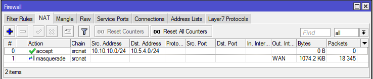
At this stage, traffic sent through the IPsec tunnel will be dropped. Both routers have NAT masquerade rules that change the source address before the packet is encrypted. The router cannot encrypt the packet because its source address no longer matches the address specified in the policy configuration. For more information, see the IPsec packet flow example.
To resolve this issue, configure a NAT bypass rule.
Site “A” router
/ip firewall nat
add chain=srcnat action=accept  place-before=0 \
 src-address=10.10.10.0/24 dst-address=10.5.4.0/24
[admin@Site "A"] > ip firewall nat print
Flags: X - disabled, I - invalid, D - dynamic
 0    chain=srcnat action=accept src-address=10.10.10.0/24 dst-address=10.5.4.0/24 log=no log-prefix=""
 1    chain=srcnat action=masquerade out-interface=WAN log=no log-prefix=""
Site “B” router
/ip firewall nat
add chain=srcnat action=accept  place-before=0 \
 src-address=10.5.4.0/24 dst-address=10.10.10.0/24
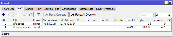
[admin@Site "B"] > ip firewall nat print
Flags: X - disabled, I - invalid, D - dynamic
 0    chain=srcnat action=accept src-address=10.5.4.0/24 dst-address=10.10.10.0/24 log=no log-prefix=""
 1    chain=srcnat action=masquerade out-interface=WAN log=no log-prefix=""
Note
If you attempted to establish the IPsec connection before adding the NAT bypass rule, clear the existing connection from the connection tracking table or restart both routers.
The bypass rule must be placed above all other NAT rules.